

systemypomiarowe.pl

Close-up of the assembled P161002 board with Microchip devices in SMD packages Board visualisation with an STM32 microcontroller, SD card socket and GPS module Three-dimensional visualisation of a board with a relay, buzzer and connectors Part of a schematic with an INA326 instrumentation amplifier and MCP3304 A/D converter Three-dimensional visualisation of a densely populated communication module board Device front panel with labelled buttons, volume knobs and a speaker Technical drawing of the front panel showing the layout of buttons and knobs Assembled board with a PIC18F2550 microcontroller, USB socket and trimmer potentiometers TouchGFX interface source code for STM32 in the Visual Studio Code editor Printed circuit board layout with copper layers and component placement
Main page Offer

Relay controller with 4 outputs / 4 inputs

The device has four output channels switched by relays. All of them are configured as changeover contacts. It is fitted with an RC5 standard infrared receiver and with a PP interface. The maximum output current is 8 A per channel at up to 250 V. It also provides four isolated digital control inputs. The supply voltage is 12 V DC at 0.2 A.
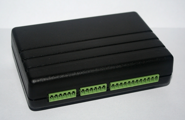
Relay controller with 4 outputs and 4 inputs - view of the enclosure

Fig. The device.

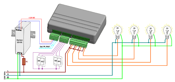
Diagram of the controller with four relay outputs and four inputs

Fig. Example wiring diagram - room lighting control.
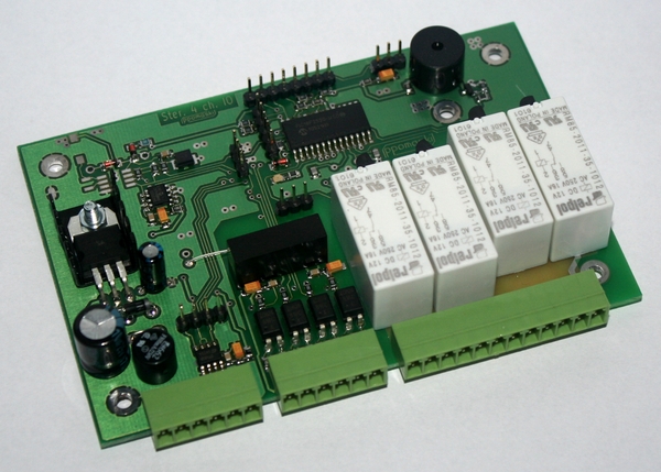
Inside the 4/4 relay controller with the output relays

Fig. For the curious - what is inside.


Copyright ©2026 systemypomiarowe.pl.