 PL
PL ENG
ENG RUS
RUS UA
UA



Raspberry Pi and eZ430-RF2500 (MSP430)
I decided to attach a TI eZ430-RF2500 module to the Raspberry Pi.
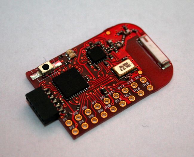
Fig. The eZ430-RF2500 module.
To do that I soldered a 2.54 mm pin header onto the battery board and connected those pins to the Raspberry Pi with wires.
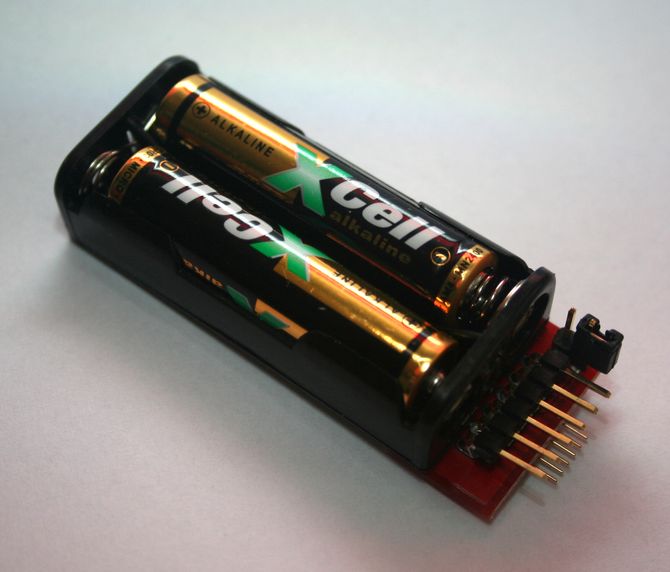
Fig. The soldered pin header.
CAUTION! Make sure that jumper JP1 on the battery board is open or removed. I assume that the changes to /boot/cmdline.txt and /etc/inittab that free the port for our own use have been made, as described in the article about the UART port. Connect the eZ430-RF2500 module to the Raspberry Pi board according to the diagram.
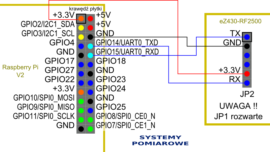
Fig. Wiring diagram of the eZ430-RF2500 and the Raspberry Pi.
After powering up the Raspberry Pi and logging in, we start the previously installed minicom program at 9600 bps with the command:
minicom -b 9600 -o -D /dev/ttyAMA0
Temperature readings from the attached module should appear on the screen.
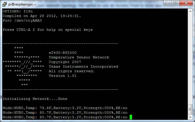
Fig. Temperature readings from the eZ430-RF2500.
If we have more complete modules, each with its battery board, we can switch them on. A TI SimpliciTI(r) network is then formed.
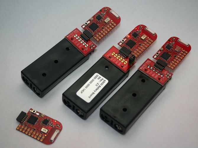
Fig. Three complete eZ430-RF2500 modules.
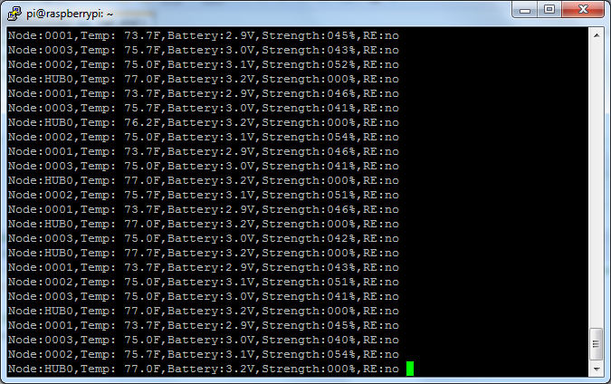
Fig. The terminal showing readings from several eZ430-RF2500 modules.
Sample readings from the modules in text form:
Node:0001,Temp:
73.7F,Battery:2.9V,Strength:044%,RE:no
Node:HUB0,Temp: 77.7F,Battery:3.2V,Strength:000%,RE:no
Node:0002,Temp: 75.0F,Battery:3.1V,Strength:052%,RE:no
Node:0003,Temp:
71.9F,Battery:3.0V,Strength:041%,RE:no
Node:HUB0,Temp:
77.7F,Battery:3.2V,Strength:000%,RE:no
Node:0001,Temp: 73.7F,Battery:2.9V,Strength:045%,RE:no
Node:0003,Temp: 71.2F,Battery:3.0V,Strength:039%,RE:no
Node:0002,Temp:
75.0F,Battery:3.1V,Strength:053%,RE:no
Node:HUB0,Temp: 78.4F,Battery:3.2V,Strength:000%,RE:no
Node:0001,Temp:
73.7F,Battery:2.9V,Strength:045%,RE:no
Node:0003,Temp: 71.2F,Battery:3.0V,Strength:039%,RE:no
Node:HUB0,Temp: 77.7F,Battery:3.2V,Strength:000%,RE:no
Node:0002,Temp:
74.3F,Battery:3.1V,Strength:052%,RE:no
Node:0001,Temp: 73.7F,Battery:2.9V,Strength:044%,RE:no
Node:HUB0,Temp: 78.4F,Battery:3.2V,Strength:000%,RE:no
Node:0003,Temp:
71.2F,Battery:3.0V,Strength:040%,RE:no
Node:0001,Temp: 73.7F,Battery:2.9V,Strength:045%,RE:no
Node:0002,Temp: 75.0F,Battery:3.1V,Strength:053%,RE:no
Node:HUB0,Temp:
77.7F,Battery:3.2V,Strength:000%,RE:no
Node:0003,Temp: 71.9F,Battery:3.0V,Strength:039%,RE:no
Node:0001,Temp: 73.7F,Battery:2.9V,Strength:044%,RE:no
Node:HUB0,Temp:
77.7F,Battery:3.2V,Strength:000%,RE:no
We can see the node number, the temperature at that point, the supply battery voltage, the radio signal strength and the operating state of the module. In a later part I will deal with interpreting these results using a purpose-written application.
Wireless transmission of sensor data is a typical task for a measurement system - we used a similar solution in our measuring probe. We build measurement data acquisition systems to order.
Copyright ©2026 systemypomiarowe.pl.