 PL
PL ENG
ENG RUS
RUS UA
UA


Raspberry Pi - I2C and driving an RGB LED
To drive an RGB LED I used the KAmodRGB test board. The board carries an RGB LED and a red LED. A PCA9633 chip, controlled over the I2C interface, is used to drive them. The same chip is also used in the expansion card I designed for the Raspberry Pi and called the Frontpanel. A simple application described in the "PHP application" document was written to control this and other modules.
CAUTION! When connecting the KAmodRGB module, pay attention to the supply voltage. The module also works correctly at 3.3 V, and connecting it to 5 V as the marking on the printed circuit board suggests may damage the GPIO lines of the Raspberry Pi.
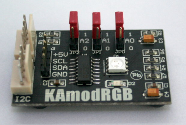
Fig. The KAmodRGB module.
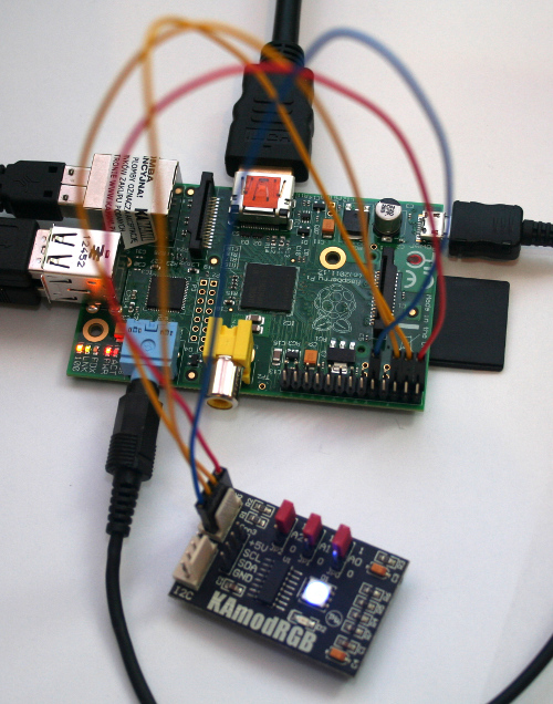
Fig. The connected KAmodRGB module.
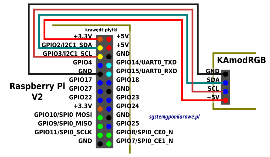
Fig. Wiring diagram of the KAmodRGB module and the Raspberry Pi.
Once the connections shown above are made, the wiringPi and libi2c-dev software described on the GPIO page has to be installed. The i2ctools diagnostic package may also be useful. To install it, issue the command:
sudo apt-get install i2ctools
Two files have to be modified: /etc/modprobe.d/raspi-blacklist.conf and /etc/modules. In the first one we comment out the lines to obtain the result shown below, by adding the # comment character:
#
blacklist spi-bcm2708
# blacklist i2c-bcm2708
In the second file we add the line:
i2c-dev
Installing the i2ctools package gives us access to an interesting application called i2cdetect. Running it as:
sudo i2cdetect -y 1
displays information about every chip attached to the I2C bus. This function is described in more detail in the article about the Frontpanel for the RPi. The digit 1 in the command means that it will report on bus number 1, which is the one available on version 2 of the Raspberry board. Version 1 provided bus number 0.
With these packages installed we can write data to chips over that bus. The i2cset command is available for writing. Example use:
sudo i2cset -y 1 0x07 0x08 0xff
In the example above the digit 1 is the bus number, 0x07 is the device address, 0x08 is the address of the register we want to write to and 0xff is the value to be written there. To configure the PCA9633 chip correctly we write the following values in turn:
sudo
i2cset -y 1 0x07 0x00 0x00
sudo i2cset -y 1 0x07 0x01 0x00
sudo i2cset -y 1 0x07 0x08 0xff
sudo i2cset -y 1 0x07 0x02 0xff
sudo i2cset -y 1 0x07 0x03 0xff
sudo i2cset -y 1 0x07 0x04 0xff
sudo i2cset -y 1 0x07 0x05 0xff
To read the value from a given address we issue the command:
sudo i2cget -y 1 0x07 0x4
The syntax of this command is analogous to the i2cset command described above.
We also took RGB lighting control all the way to a finished device - see the RGBW LED controller. If you need your own version of such a circuit, have a look at our offer.
Copyright ©2026 systemypomiarowe.pl.