 PL
PL ENG
ENG RUS
RUS UA
UA

Raspberry Pi - GPIO port
Configuring and using the GPIO port
To test working with the GPIO port I used the KAmodLED8 test board. The board carries a 74LVC541 octal buffer and eight LEDs. This arrangement does not load the ports of the processor on the Raspberry Pi board, which would happen if the LEDs were connected directly.
The signals on the P1 header of the Raspberry Pi are laid out as shown in the figure.
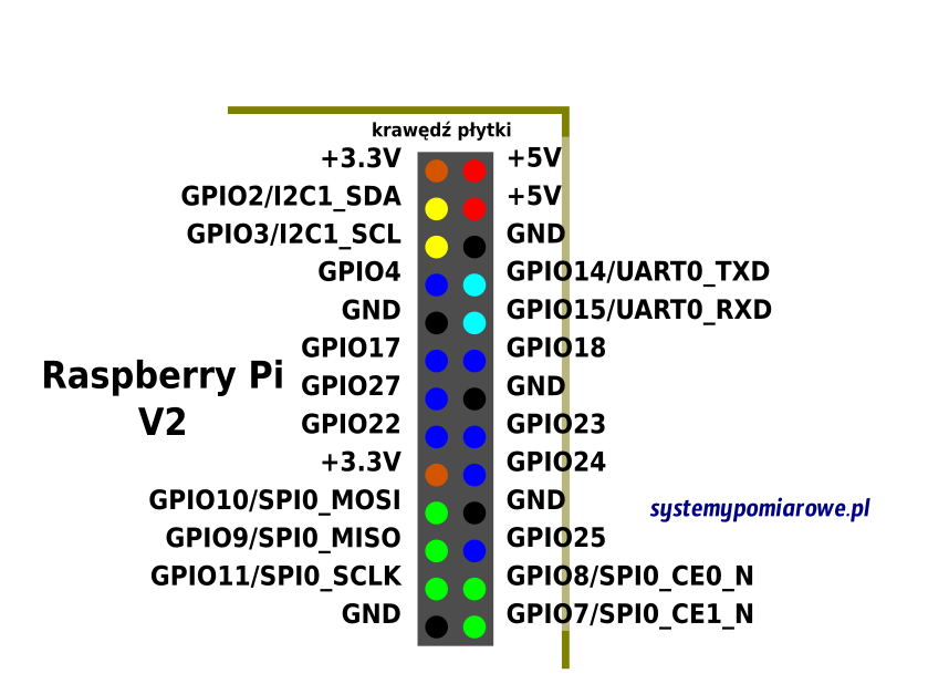
Fig. Signal layout on the P1 header of version 2.
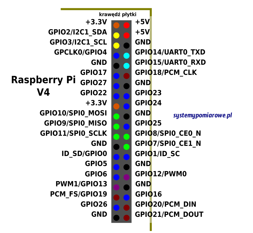
Fig. Signal layout on the P1 header of version 4.
How the KAmodLED8 module is connected.
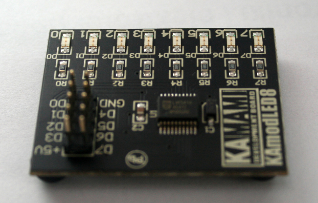
Fig. The KAmodLED8 module.
The module was connected to the P1 header according to the diagram below.
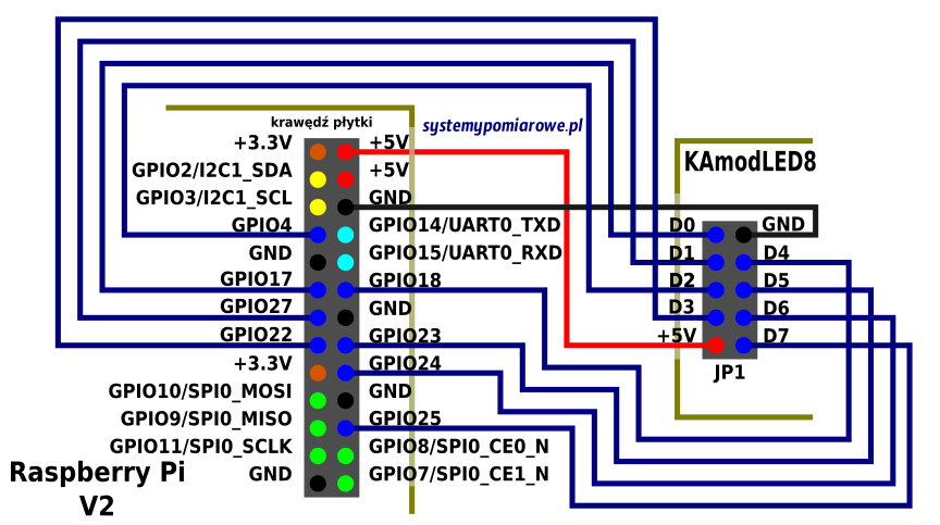
Fig. Wiring diagram of the KAmodLED8 module and the Raspberry Pi.
Wires with specially prepared ends were used for the connection. The connected module is shown in the figure below.
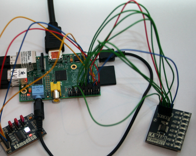
Fig. The connected KAmodLED8 module.
The connections were made so as to leave the SPI, I2C and UART interfaces free for other uses. On the header drawing these are the signals marked in blue.
To use the GPIO port we need the wiringPi package, which lets us set the direction and the states of individual GPIO outputs from the command line. So we have to download and compile it. It can be obtained from https://projects.drogon.net/raspberry-pi/wiringpi/ and then unpacked in the home directory.
tar xfz wiringPi.tgz
We should also install the library supporting the I2C standard, because compiling wiringPi may otherwise fail. To do that we issue the command:
sudo apt-get install libi2c-dev
To compile the library we run the following commands in turn:
cd
wiringPi/wiringPi
make
sudo make install
cd ../gpio
make
To drive a GPIO output line we issue the command:
sudo ./gpio -g mode 4 out
where 4 is the GPIO line number and "out" means that we configure the line as an output. To set state 1 on the configured GPIO line we type:
sudo ./gpio -g write 4 1
where 4 is the GPIO port number and 1 is the logic state on that output. Sometimes a GPIO line has to be read. Once it is configured as an input, using the "in" parameter, we read it from the command line with:
sudo ./gpio -g read 4
The GPIO port is enough for simple experiments, but with more signals a dedicated expansion board is needed - such as the frontpanel for the Raspberry Pi we describe. We design and build such modules to order.
Copyright ©2026 systemypomiarowe.pl.