 PL
PL ENG
ENG RUS
RUS UA
UA
Raspberry Pi - frontpanel (expansion module)
The control panel board for the Raspberry Pi.
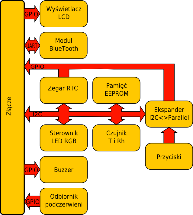
Fig. Block diagram of the expansion card.
Inspired by my earlier experiments with the Raspberry Pi, I decided to design and build a board combining the features of all the previous examples. The interface has six backlit buttons connected through an MCP23008 chip to the I2C interface. The control panel is fitted with an alphanumeric LCD display. It is driven with the wiringPi library described in another article, which has built-in functions for displays of this type. A PCA9633 chip is used to control the display backlight. The display has RGB backlighting, so its colour can be defined freely. The board also carries a PCF8563 RTC clock connected to the I2C interface. An SHT21 chip, a digital thermometer and hygrometer, is attached to the same interface. A 24C02 memory chip is built into the panel for storing the current settings. A large functional block built into the panel is a BTM222 UART to BlueTooth converter. That interface gives us a new communication channel to the Raspberry Pi board. A 2.4 GHz antenna is attached to the BTM222 module. Another interesting component fitted on the control panel board is a TSOP4836 infrared receiver, which together with the lirc library allows an interesting way of controlling the Raspberry Pi. A buzzer driven from the GPIO interface of the Raspberry Pi is fitted on the board as well. As mentioned above, several chips on the control panel board are attached to a common I2C control interface. To communicate with them we need to know their addresses. They are given in the table below.
| address | chip | notes |
|---|---|---|
| 0x0c | PCA9633 | |
| 0x51 | PCF8563 | |
| 0x52 | AT24C02 | 0xa2 per the datasheet |
| 0x40 | SHT21 | |
| 0x20 | MCP23008 |
These addresses differ from the ones given in the datasheets of the individual chips. The reason is that the datasheets give the eight-bit address together with the read/write bit, whereas the wiringPi library uses only the seven most significant bits, so the "datasheet" address has to be divided by two, for example 0xa2/2 = 0x52.
The table below shows how the LCD display is connected to the GPIO interface.
| RS | EN | D4 | D5 | D6 | D7 |
|---|---|---|---|---|---|
| GPIO25 | GPIO7 | GPIO22 | GPIO27 | GPIO17 | GPIO4 |
As written earlier, the LCD display used has built-in RGB backlighting. A PCA9633 chip drives that
backlight. The R colour is controlled by the register at address 0x05, the G colour by the register at address
0x04 and the B colour by register 0x03. The keypad backlight is controlled by the register at address 0x02. An
MCP23008 chip is used to read the state of the keypad. Its interrupt output is connected to the
GPIO24 line. After detecting a change on that line, the program running on the Raspberry Pi should read from the
MCP chip which button was pressed.
The receiver of infrared remote control signals is
connected to the GPIO18 line. The lirc library has to be configured to take that into account.
There is nothing
to describe about the BTM222 module and the way it is connected. It is attached to the RXD and TXD lines. The RESET
line of the BTM222 module is connected to pin
GP7 of the MCP23008.
The buzzer is connected to the GPIO23 line of the Raspberry Pi board. A connector wired to
the SPI interface of the Raspberry Pi is fitted on the board. For anyone needing to attach further chips with an
I2C interface, there is
also a connector carrying the I2C interface signals.
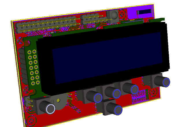
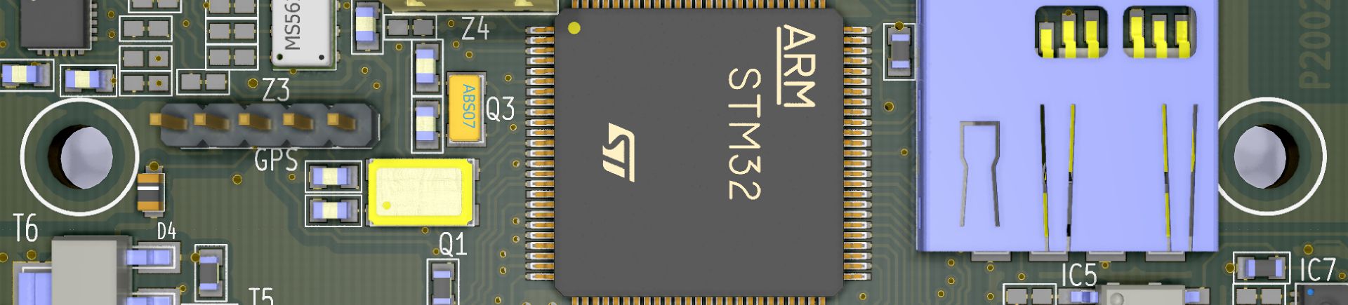
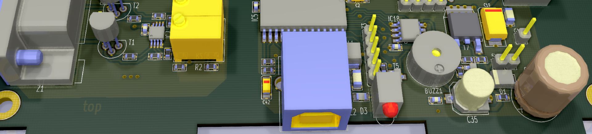
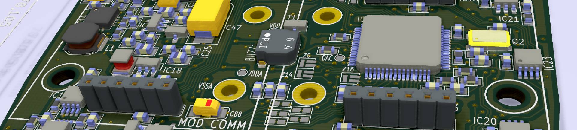
Fig. The frontpanel designed for the Raspberry Pi.
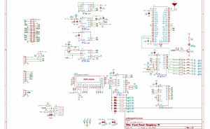
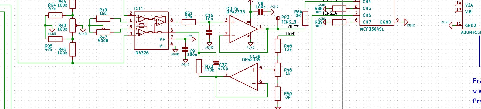
Fig. Schematic of the frontpanel.
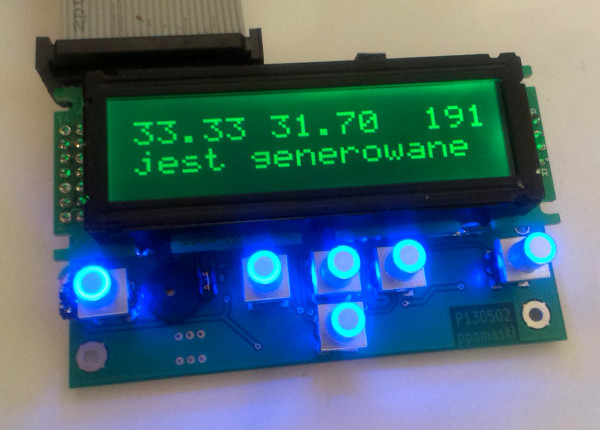
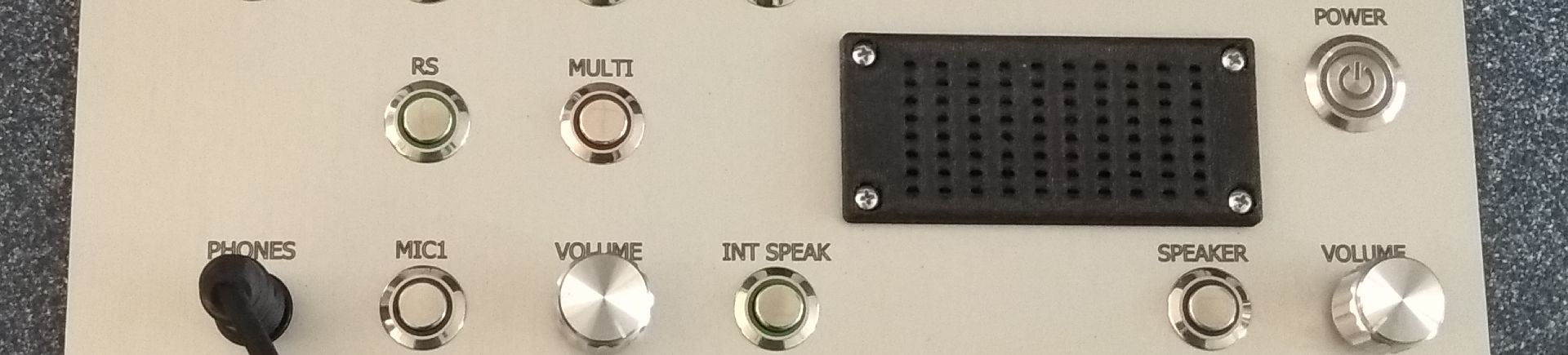
Fig. The assembled and working frontpanel.
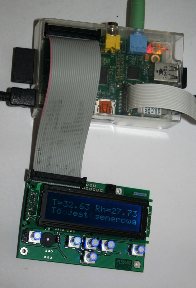
Fig. One more view: the RPi and the frontpanel.
The printed circuit board.
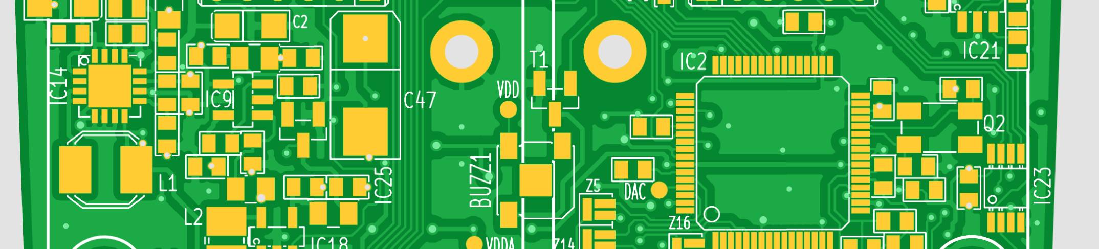
A double-sided printed circuit board carrying all the components and connectors was designed on the basis of the schematic.
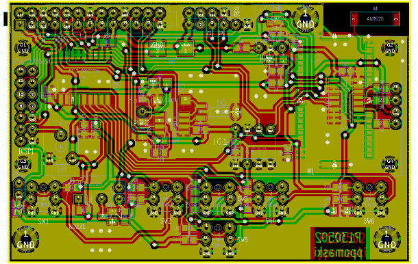
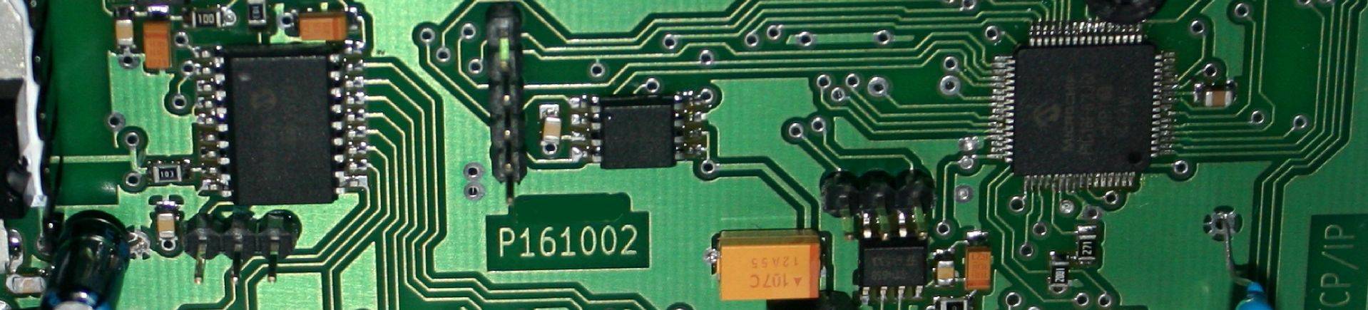
Fig. The printed circuit board as designed.
Application - LCD
I started commissioning the frontpanel with the LCD display. To do that, the wiringPi library has to be
installed following the instructions in the chapter about the GPIO pins. To make the display work I wrote an
application in C.
The GPIO lines used have to be configured. This can be done with the lcdInit function and the following
parameters:
fd3
= lcdInit (2,16,4,6,11,3,2,0,7,0,0,0,0);
The parameters are, in order:
2 - the number of display rows
16 - the number of characters per row
4 - the width
of the data interface
6 - the wiringPi pin number for RS
11 - the pin for EN
3 - the pin
for D0
2 - the pin
for D1
0 - the pin for D2
7 - the pin for D3
the remaining zeros are D4 to D7. fd3 is
a handle to the display used in the functions that follow. When configuring this display, pay attention to the
numbering
of the GPIO lines. In the chapter about the GPIO port the line numbers followed the Raspberry Pi documentation.
The numbering used when programming with the wiringPi library is different. Issuing the command gpio readall gives
a table whose columns contain:
- the pin number for the wiringPi library
- the pin number
according to the Raspberry Pi documentation
- the function of the port
- the logic value on the input
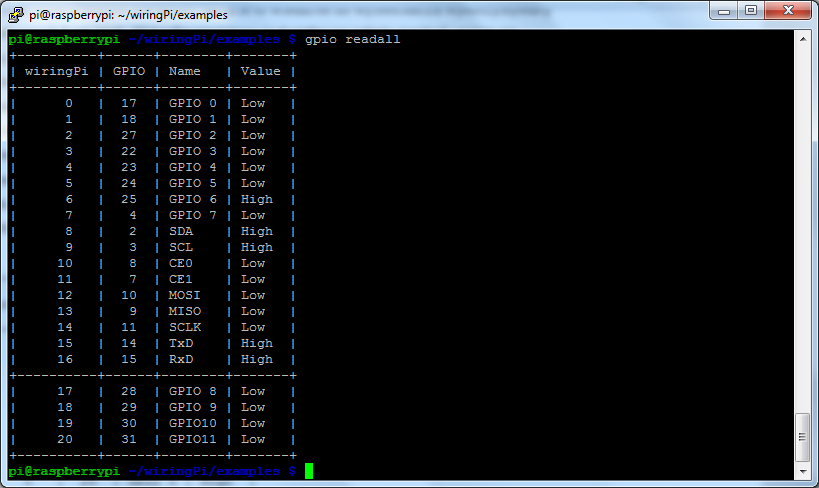
Fig. Logic states on the P1 and P5 headers.
The next functions are:
lcdPosition
(fd3, 0, 0);
This function sets the cursor of display fd3 to row 0, position 0.
lcdPuts
(fd3, " some text ");
This function shows the text in quotation marks on display fd3. The functions
presented above
are enough to display text on the screen.
The I2C interface
The wiringPi library described earlier is used to handle the I2C bus. Its installation and
configuration were described in another document, about driving the RGB LED controller module.
Once the
frontpanel is correctly connected and the command scanning
the I2C interface is issued
sudo
i2cdetect -y 1
we should get something like this:
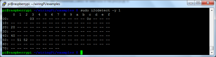
Fig. The result of the i2cdetect function.
The GPIO interface for remote control.
The remote control module is described in another article.
More to follow shortly
The frontpanel described here was taken from the schematic through the printed circuit board to the driver software. That is exactly the scope in which we carry out electronic projects for our clients - including the choice of display, the PCB design and the enclosure.
Copyright ©2026 systemypomiarowe.pl.