 PL
PL ENG
ENG RUS
RUS UA
UA
Raspberry Pi - UART port
The P1 header provides the UART0 port, specifically the UART0_TXD and UART0_RXD signals. Any device with a serial link can be attached to it. I connected a board designated P120205, fitted with a BTM-222 BlueTooth module.
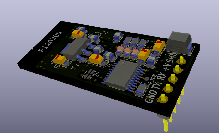
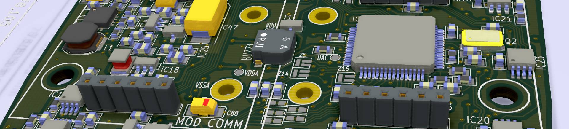
Fig. The P120205 board designed in KiCad.
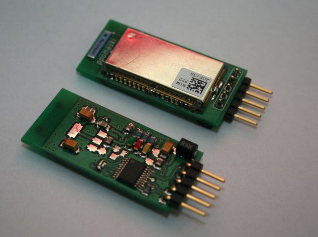
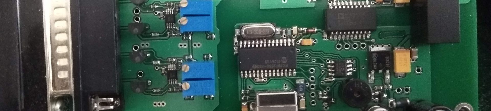
Fig. The manufactured P120205 board.
When connecting the board, pay attention to the supply voltage, which for the Raspberry Pi should be 3.3 V, and to the fact that the RX signal of the board has to go to UART0_TXD, while the TX signal of the P120205 board has to go to the pin marked UART0_RXD on the Raspberry Pi. The wiring diagram is shown in the figure below.
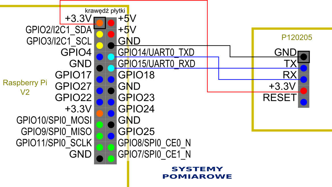
Fig. Wiring diagram of the P120205 board.
Once the connections are made, the PC has to be attached over the newly created link. On a computer running Windows, in my case Windows 7 Home Edition, we right-click the Bluetooth Devices icon and then choose Add a device.

Fig. The "Bluetooth Devices" icon at the bottom of the screen.
After a moment our "Serial Adaptor" device should appear in the window. We right-click its icon again and choose "Add a device". Then we click "Enter the device pairing code" and give the code 1234. The drivers will be installed and we can connect to the computer.
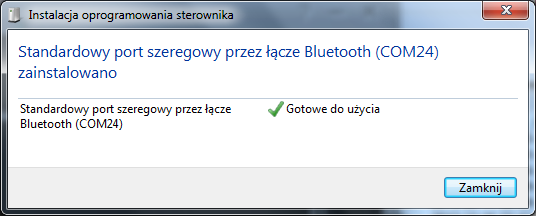
Fig. The "Installing software..." window
Next, in Control Panel -> System -> Device Manager -> Ports (COM and LPT) we identify the COM port number, COM24 in my case.
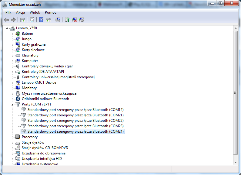
Fig. Device Manager with the serial port visible.
Once the port number is known, we start PuTTY and enter the configuration shown in the illustration below:
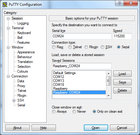
Fig. The PuTTY configuration window.
To connect to the Raspberry Pi we press the "Open" button. And here comes a small surprise, because we may get a window similar to the one below.
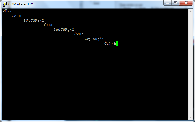
Fig. The PuTTY terminal window.
These garbled characters come from the fact that the Raspberry has a UART link working at 115200 bps by default, while the factory speed of the P120205 board is 19200 bps. To make the speeds match, the speed of the Raspberry Pi has to be changed to 19200 for a moment and the P120205 board configured. To do that, close the PuTTY terminal window. Using a terminal connected over ssh, or directly on the monitor attached to the Raspberry Pi, log in and edit the /boot/cmdline.txt file, which contains the entry:
dwc_otg.lpm_enable=0 console=ttyAMA0,115200 kgdboc=ttyAMA0,115200 console=tty1 root=/dev/mmcblk0p2 rootfstype=ext4 rootwait
Every 115200 value has to be changed to 19200. In the /etc/inittab file, in the line:
T0:23:respawn:/sbin/getty -L ttyAMA0 115200 vt100
the value 115200 has to be changed to 19200 as well. After these changes and a restart of the Raspberry Pi we can log in through a terminal connected over the BlueTooth interface.
If we want to use the UART link for our own purposes, or to change settings of the P120205 module such as the PIN code or the transmission speed, we have to install a terminal program and modify some files. Minicom will do. To install it we type:
sudo apt-get install minicom
In /boot/cmdline.txt the entries concerning the ttyAMA1 device have to be removed, so the line changed earlier should now look like this:
dwc_otg.lpm_enable=0 console=tty1 root=/dev/mmcblk0p2 rootfstype=ext4 rootwait
In /etc/inittab the following line has to be commented out with #:
#T0:23:respawn:/sbin/getty -L ttyAMA0 115200 vt100
Then restart the Raspberry Pi. Now we can start a terminal with the given parameters:
minicom -b 19200 -o -D /dev/ttyAMA0
To change selected parameters, consult the documentation of the BT222 module, in particular the AT commands. I changed the device name to RPI001, changed the PIN code, turned echo off and so on.
ATN=RPI001
ATX0
ATP=12345678
ATM0
ATK0
ATE0
ATL5
Each command should be answered with OK. If we get ERROR, something went wrong and the command has to be repeated. Since I changed the speed to 115200 with the ATL5 command, minicom has to be closed. To leave minicom press Ctrl-A, then x, and confirm with Enter. Minicom then has to be started again with the following parameters:
minicom
-b 115200 -o -D /dev/ttyAMA0
ATQ1
ATI?
We should get something similar to:
F/W VERSION: v6.26
We leave minicom again with Ctrl-A, then x, confirming with Enter. From this moment we have a fully working and programmable UART interface.
The P120205 Bluetooth board used here is our own design. We design and build similar communication modules to order - UART, RS485, Ethernet or Bluetooth.
Copyright ©2026 systemypomiarowe.pl.